
A Practical Guide to Zero Trust Security: Implementing Network Segmentation with pfSense, MFA with Authy, and Continuous Monitoring Using Splunk#

Introduction
The aim of this project was to implement a basic Zero Trust Architecture as a practical demonstration of modern security principles. Zero Trust operates under the philosophy of “never trust, always verify,” ensuring that every access request is validated and that sensitive resources are segmented from general user access.
This activity involved three key components:
- Network Segmentation: Using pfSense to create isolated VLANs for general users and sensitive systems, with strict access controls.
- Multi-Factor Authentication (MFA): Configuring Authy to secure system access with an additional layer of verification beyond passwords.
- Continuous Monitoring: Using Splunk to monitor network activity, detect anomalies, and establish real-time alerts for suspicious behavior.
By the end of this project, we will achieve:
- A segmented network where general users are restricted from accessing sensitive systems.
- Strong authentication mechanisms that prevent unauthorized access.
- A monitoring system to track user and device activity for proactive threat detection.
This hands-on activity is designed not only to enhance your technical skills in configuring security tools but also to provide a comprehensive guide for others looking to implement a Zero Trust model. Each step is documented with clear explanations, practical tests (e.g., ping commands), and screenshots to ensure replicability.
Step 1: Install and Configure pfSense
The first step is setting up pfSense to implement network segmentation, which is a cornerstone of Zero Trust Architecture.
1. Install pfSense
- Download pfSense:
- Visit pfSense Official Download Page{.markup–anchor .markup–li-anchor data-href=“ https://www.pfsense.org/download/" rel=“noopener” target="_blank”}.
- Choose the appropriate installer for your system.
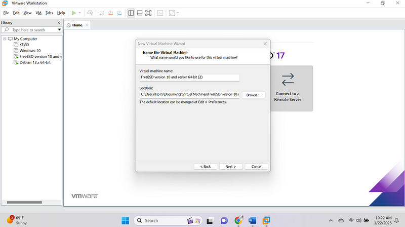
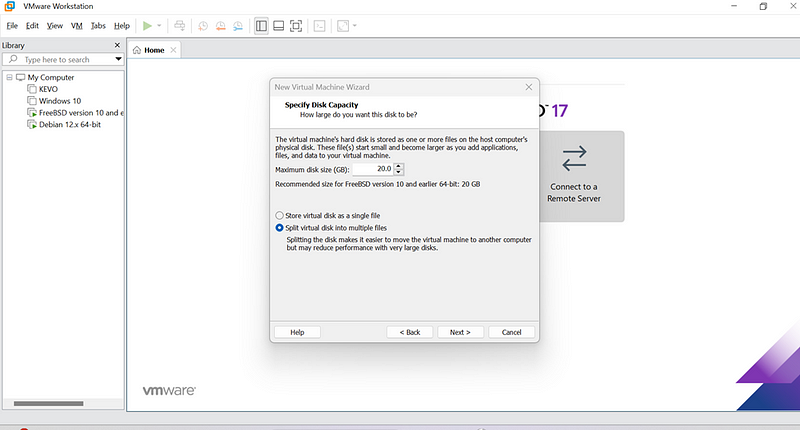
- Set Up pfSense in a Virtual Environment (e.g., VMware):
- Create a new virtual machine with these configurations:
- CPU: 2 vCPUs
- RAM: 4GB
- Storage: 16GB
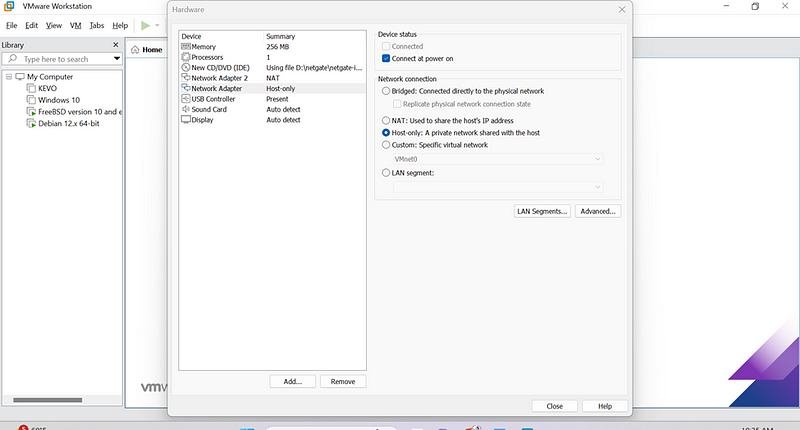
- Two network adapters:
- WAN: Connect to your internet source.
- LAN: Connect to the internal network.
Next to:
- Boot and Install:
- Boot the virtual machine with the pfSense ISO.Follow the installation wizard to set up the system.
- Assign network interfaces:
- WAN: Default to your external network.
- LAN: Internal-facing network (default: 192.168.88.1).
(n/b make sure you create the two adapter one for WAN and the other for LAN)
Our pfsense is now ready:
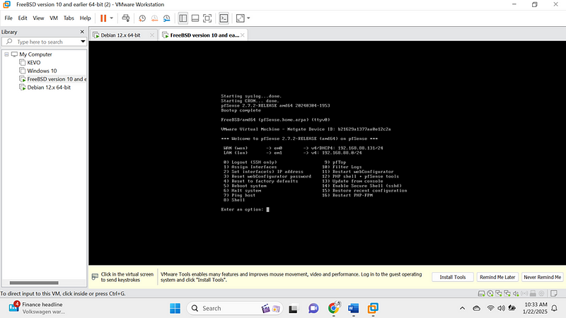
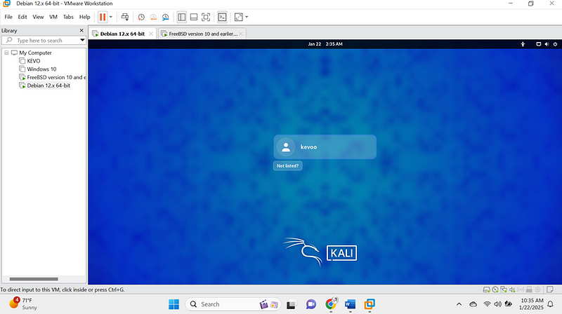
Our linux is also ready:
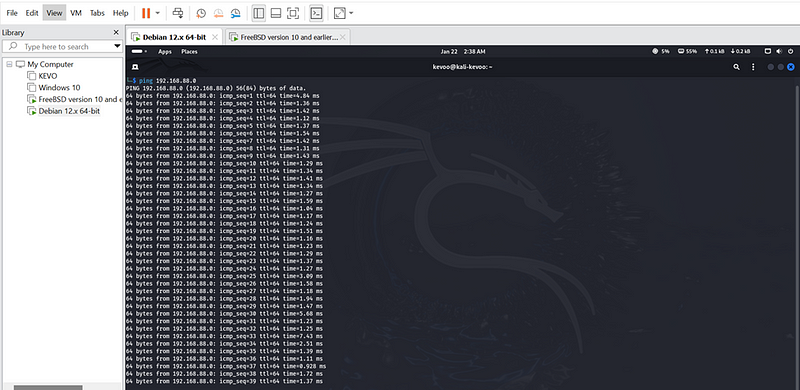
They both need to communicate first ,so
I did aping command from linux to pfsense and there was a communication.
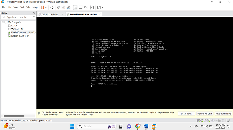
I did another ping scan from pfsense to linux:
They both communicated very well so the next step was to access the pfsense web interface from linux firefox:
4.Access the Web Interface:
- Open a browser on a machine connected to the LAN.
- Navigate to http://192.168.88.1.](http://192.168.88.1.){.markup–anchor .markup–li-anchor data-href=“http://192.168.88.1.” rel=“noopener” target="_blank"}
- Log in with the default credentials:
- Username: admin
- Password: pfsense
Then I logged using the above details to access the pfsense configuration setting.
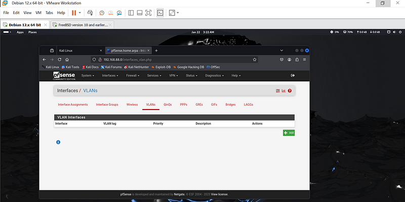
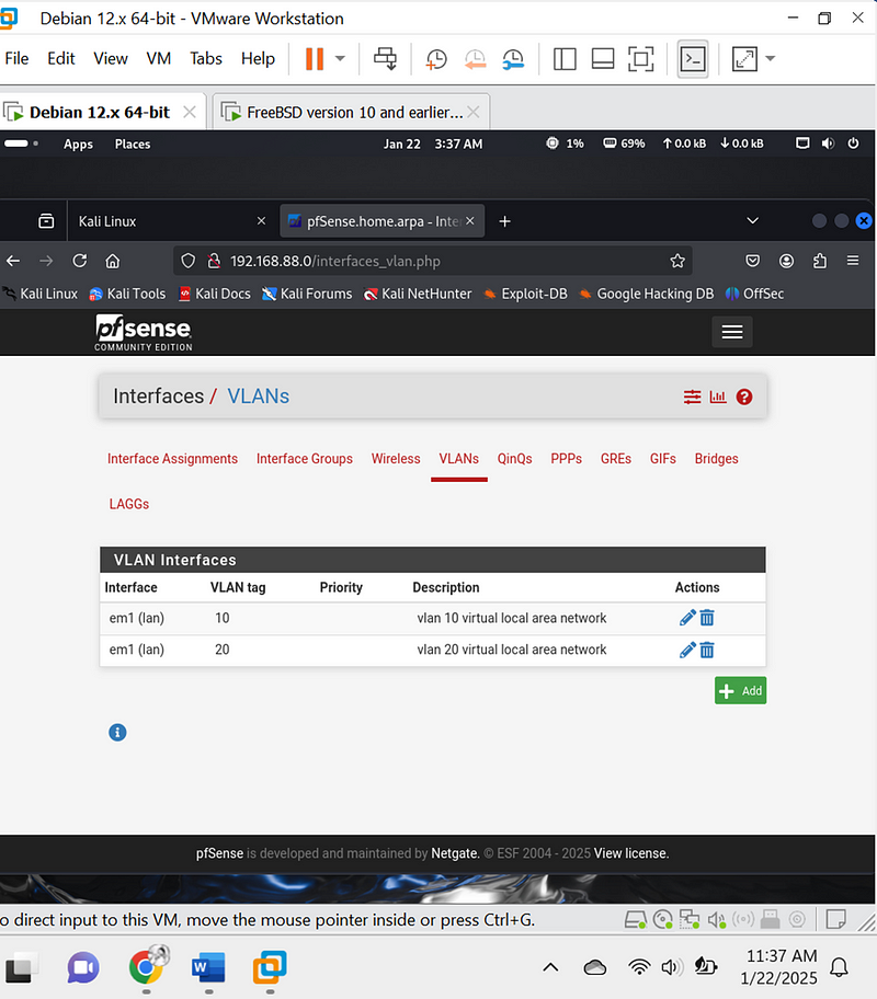
2. Create VLANs for Segmentation
- Navigate to VLAN Settings:
- Go to Interfaces > Assignments and click on the VLANs tab.
- Create Two VLANs:
VLAN 10 (virtual 10 local area network):
- VLAN ID: 10
- Parent Interface: LAN
VLAN 20 (virtual 20 local area network):
- VLAN ID: 20
- Parent Interface: LAN
- Assign VLANs to Interfaces:
- Under Interfaces > Assignments, assign the VLANs created to new interfaces.
o Go back to Interfaces > Assignments.
o Assign each VLAN to a new interface:
- VLAN 10: Add as OPT1 and rename it to VLAN 10.
- VLAN 20: Add as OPT2 and rename it to VLAN 20.

4.Configure IP Addresses for VLAN Interfaces
(n/b) for your case you are free to apply your own ip addresses:
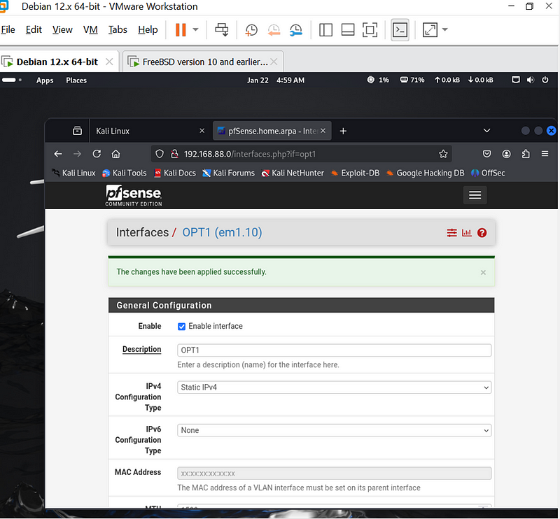
- Go to Interfaces > VLAN 10:
- Enable the interface.
- Set the static IPv4 address to: 192.168.88.1/25.
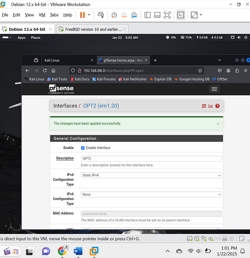
- Go to Interfaces > VLAN 20:
- Enable the interface.
- Set the static IPv4 address to: 192.168.88.129/25.
Using the above configuration ,I though they were the best reason for me being that they were under my subnets mask only to receive this error.
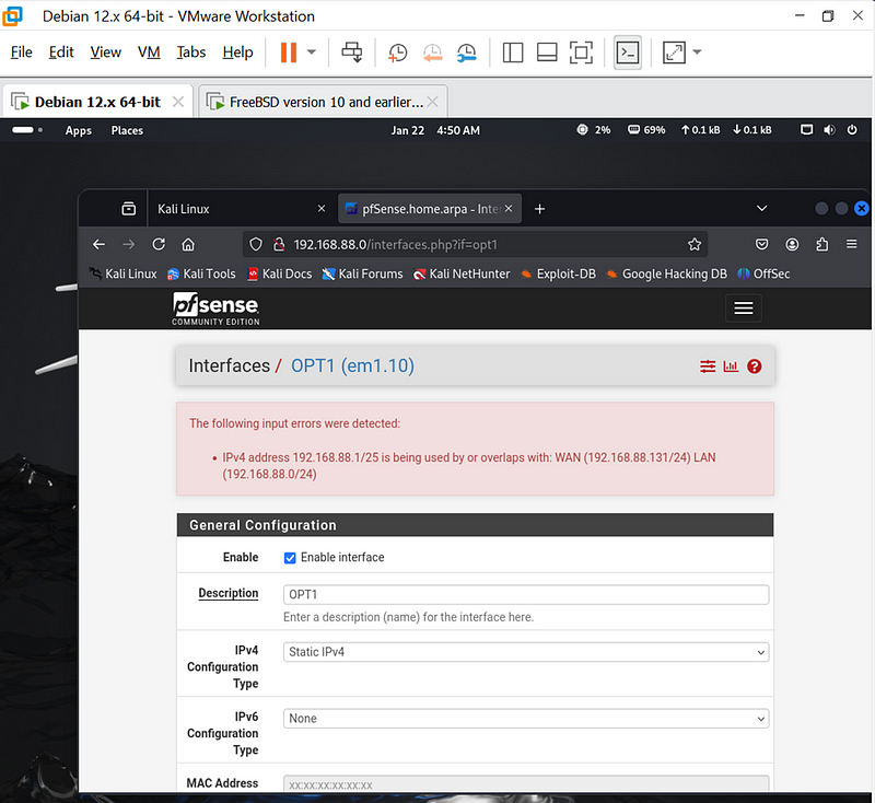
The above error occurs because my WAN and LAN interfaces are already using overlapping IP address ranges (192.168.88.0/24), and my VLANs also fall within the same range. To fix this issue, i need to adjust the IP addressing to avoid overlap.so I used a separate subnet mask
Use a Separate Subnet for VLANs
You must use a new IP range for your VLANs that does not overlap with your existing WAN or LAN subnets. For example:
- WAN: Keep 192.168.88.131/24 (existing).
- LAN: Keep 192.168.88.0/24 (existing, if necessary).
- VLAN 10 (General Users): Use 192.168.10.0/24.
- VLAN 20 (Sensitive Systems): Use 192.168.20.0/24.
For vlan 10 below it now successful.
For Vlan 20 above is now successful.
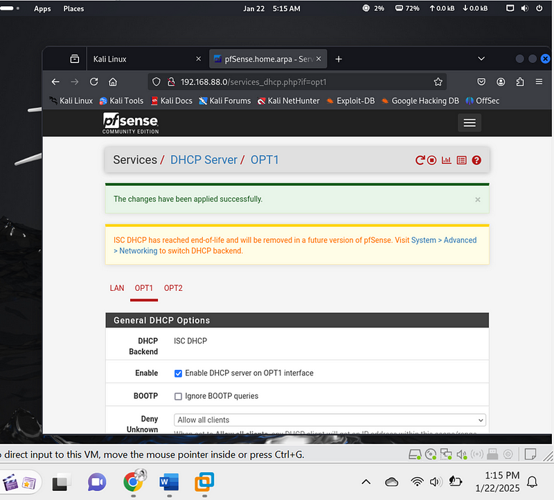
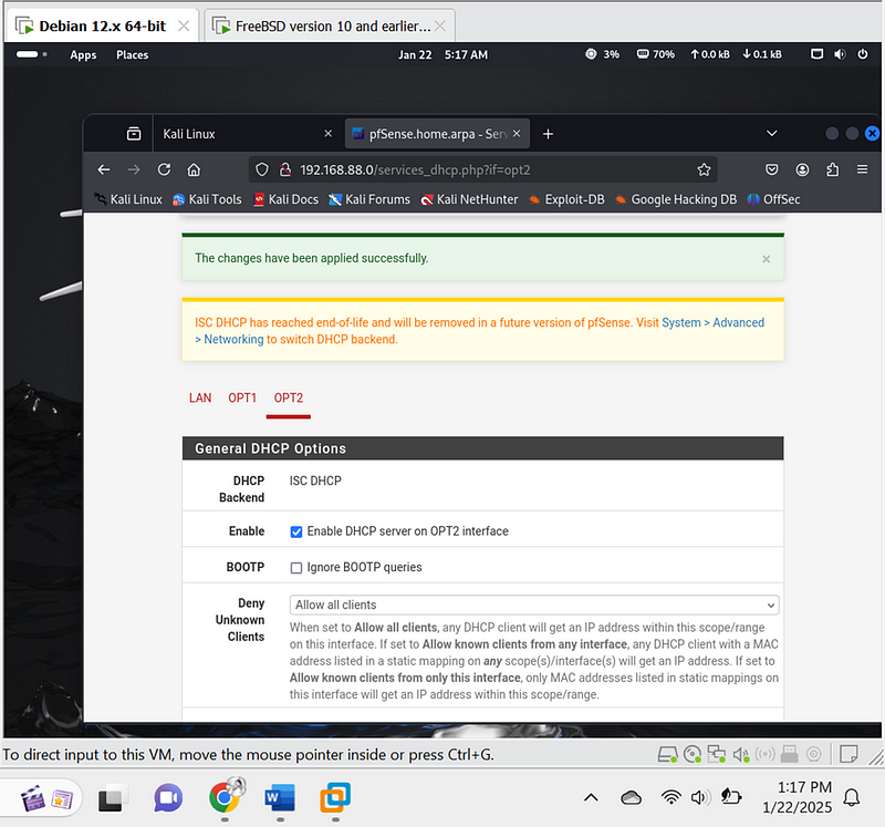
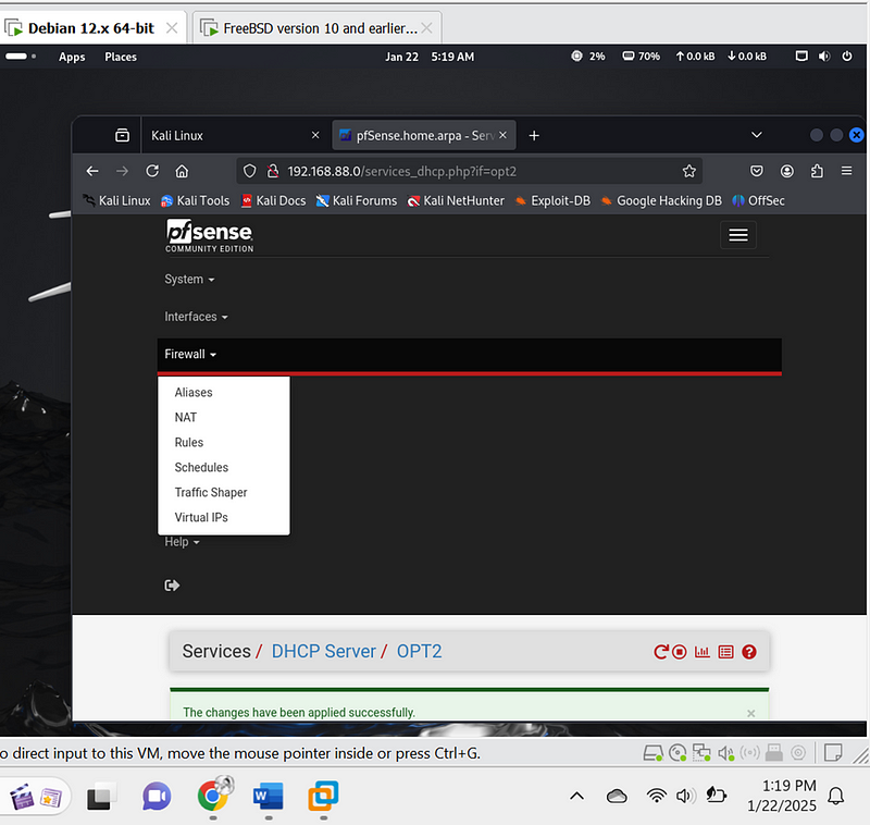
4. Set DHCP Servers for VLANs#
- Navigate to Services > DHCP Server.
- Enable DHCP for each VLAN:
- VLAN 10:
- Range: 192.168.10.10 to 192.168.10.100.
- VLAN 20:
- Range: 192.168.20.10 to 192.168.20.100.
3. Configure Firewall Rules#
- Navigate to Firewall > Rules.
2.Set up rules for each VLAN:
VLAN 10:
-Allow internet access.
-Block traffic to VLAN 20.
VLAN 20:
- Restrict access to only necessary services ( database servers).
Save and apply the changes.
Below image is for vlan 10 opt1 rules configured:
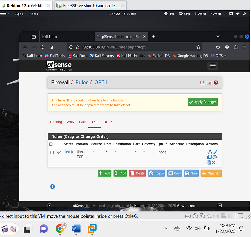
What I did:
Create Rules for VLAN 10 (Internet Access):
- Add a new rule: Click the Add button under the “Floating” tab. This will create a new rule at the top of the list.
- Set interface: Select OPT1 connected to vlan 10.
- Action: Choose Pass to allow traffic.
- Protocol: Leave as Any to allow all protocols.
- Source: Set to any to allow traffic from any source.
- Destination: Set to any to allow traffic to any destination.
- Port: Leave as Any.
- Gateway: Leave as Default.
- Schedule: Leave as Always.
- Description: Enter a descriptive name, such as “Allow Internet for VLAN 10”.
- Save the rule.
Below image is for vlan 20 opt2 rules configured:
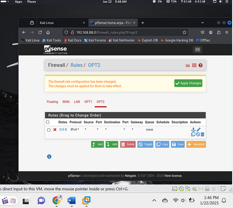
What I did**:**
· Add a new rule for the OPT2 interface (as shown in the screenshot).
· Action**:** Choose Block to deny traffic.
· Protocol**:** Leave as Any.
· Source: Set to any to block traffic from any source.
· Destination: Set to any to block traffic to any destination.
· Port: Leave as Any.
· Gateway: Leave as Default.
· Schedule: Leave as Always.
· Description: Enter a descriptive name, such as “Block all traffic for VLAN 20”.
· Save the rule.
4. Test Network Segmentation#
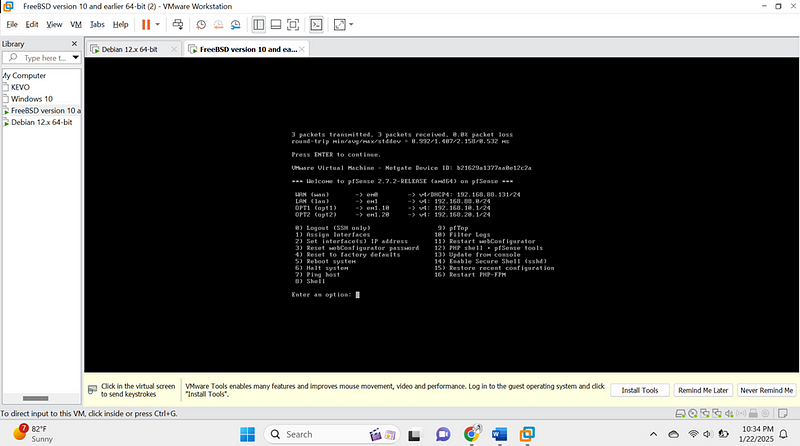
Below image shows my pfsense with both configured vlans
- Connect Devices:
- Assign one device (Linux machine) to VLAN 10.
- Assign another device (server) to VLAN 20.
- Run Ping Tests:
- From VLAN 10, run:
- ping 192.168.20.1
This should fail, indicating restricted access.
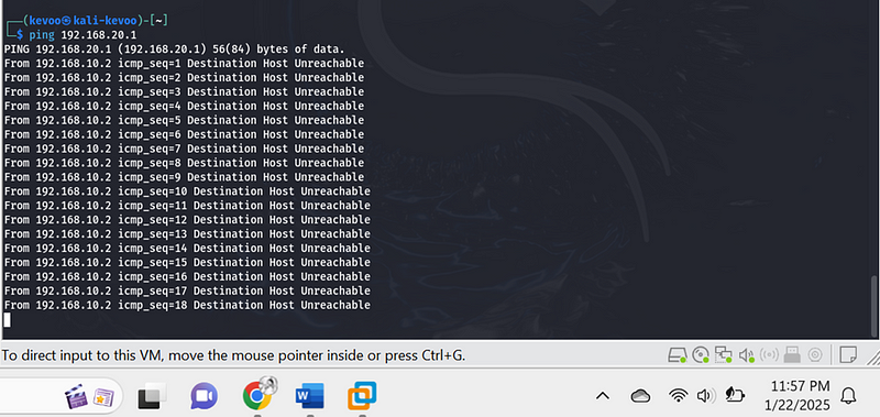
- Ping the pfSense gateway for VLAN 10:
- ping 192.168.10.2
This should succeed, verifying connectivity to the router.
.
Step 2: Implement MFA Using google authenticator with OpenVPN#
Prerequisites:#
1.pfSense Setup: Ensure your pfSense is installed and running.
2.OpenVPN Package: Installed and configured on pfSense.
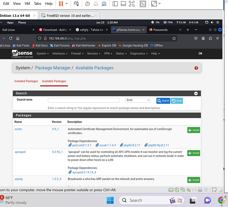
Install OpenVPN from System > Package Manager > Available Packages.
3.Google Authenticator App: Downloaded and installed on your mobile device.
4.FreeRADIUS: Installed and configured as the authentication server.
Step-by-Step Guide
1. Set Up FreeRADIUS for MFA
- Install FreeRADIUS from the pfSense package manager:
- Navigate to System > Package Manager > Available Packages.
- Search for “FreeRADIUS” and click Install.
- Configure FreeRADIUS:
- Navigate to Services > FreeRADIUS.
- Go to the Users tab and add a user:
- Username: kelvinkiplagat]{#b831}
- Password: **************
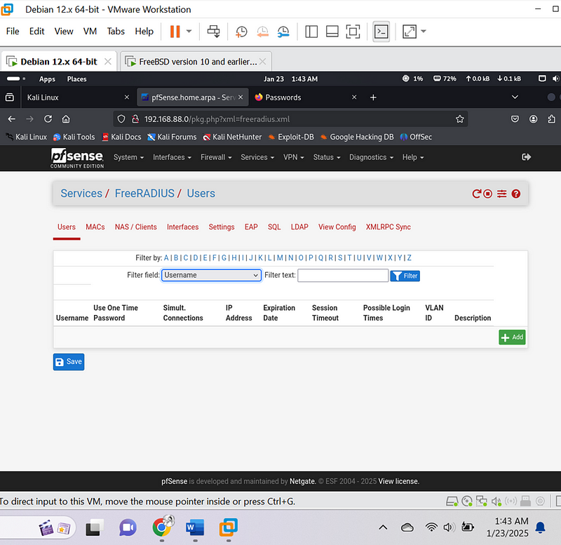
- Enable Time-Based One-Time Passwords (TOTP):
- In the FreeRADIUS configuration, enable TOTP for the user you created.
- Start the FreeRADIUS service:
- Navigate to Status > Services, locate FreeRADIUS, and click Start.
2. Enable OpenVPN on pfSense
- Navigate to VPN > OpenVPN and set up a new server:
- Choose the Wizard to simplify the configuration.
- Use the RADIUS server (FreeRADIUS) as the authentication backend.
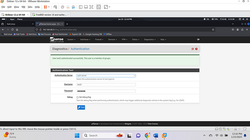
I went to the diagnostic and I did an authentication test1 and below image show that it was successful
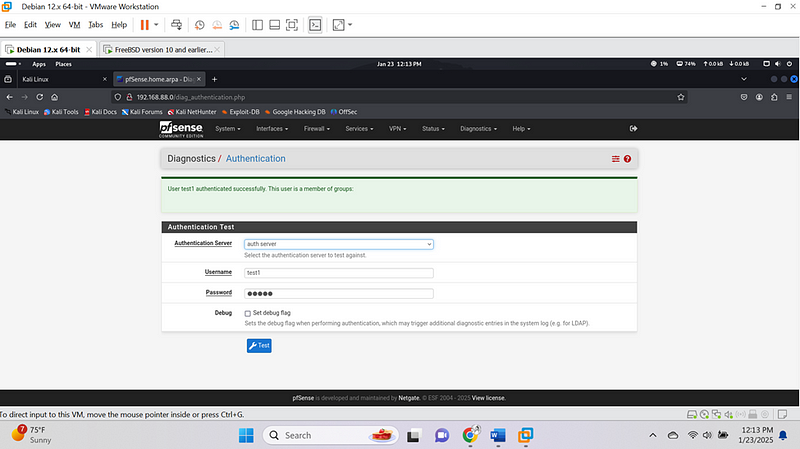
I went to the diagnostic and I did an authentication test2 and below image show that it was successful
3. Configure goohle Authenticator app for TOTP
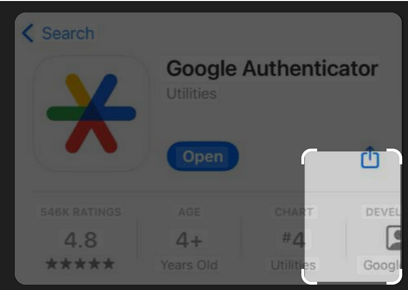
- Open the app on your mobile device.but in our case we shall be using google authentication
- dd a new account and manually set it up with the TOTP secret generated by FreeRADIUS.
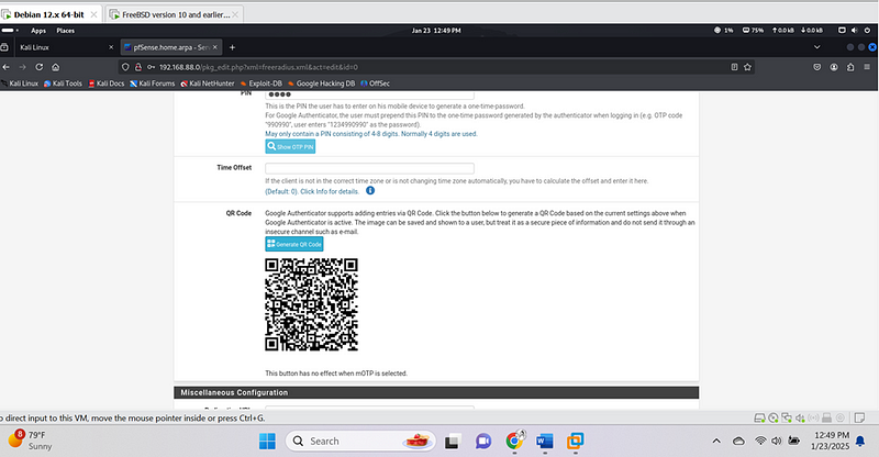
- A TOTP (6-digit code) will now be generated every 30 seconds.
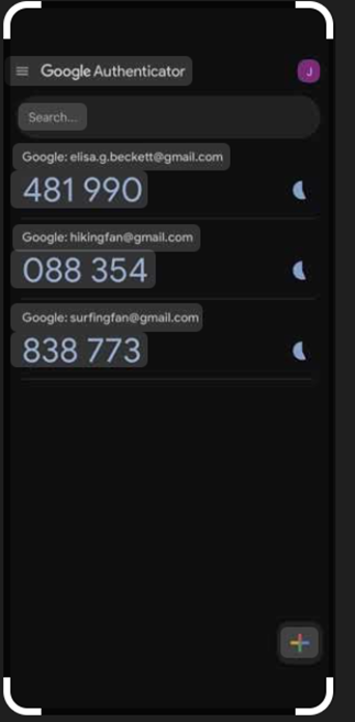
This is the google authenticator looks likes in my phone and it keeps changing every 5 seconds
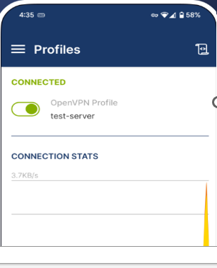
4. Test the MFA Integration#
- Connect to the OpenVPN server using a VPN client (OpenVPN Connect).
- When prompted for credentials, enter:I have hidden my credetilas
- Username:kelvin kiplagat
- Password:********
- ollowed by the 6-digit TOTP from Authy.
- For example, if your TOTP is 123456, the password will be: word123456.

3. Test the connection:
- Connection should fail if the TOTP is incorrect or missing. Via the mobile phone
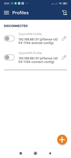
- Connection should succeed if both the static password and TOTP are correct.
Step 3: Set Up Continuous Monitoring Using Splunk on Kali Linux
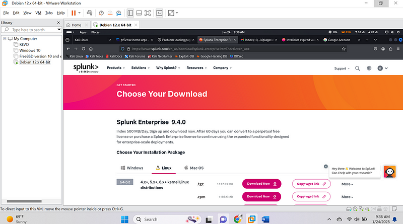
1. Install Splunk
- Download Splunk Free:
- Visit Splunk Enterprise Download Page{.markup–anchor .markup–li-anchor data-href=“ https://www.splunk.com/en_us/download/splunk-enterprise.html" rel=“noopener” target="_blank”}.]{#09bb}
- Choose the .tgz installer for Linux.
- Register or log in if prompted.
- Download the .tgz file to your Kali Linux system.
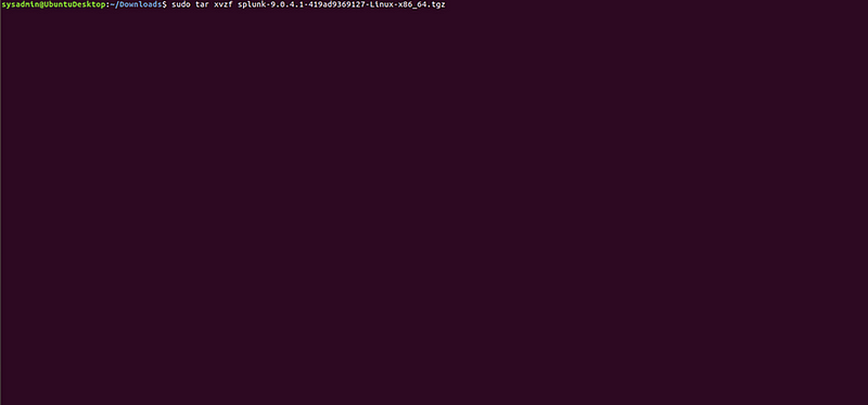
- Install Splunk:
- Open a terminal and navigate to the folder where the .tgz file is saved.
- Extract the file:
Sudo tar -xvzf splunk-9.0.4.1–419ad9369127-linux-x86_64.tgz -C /opt
cd /opt/splunk/bin
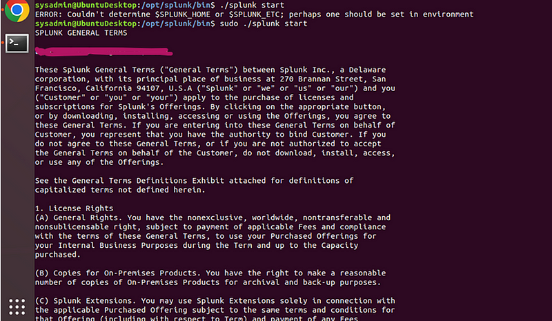
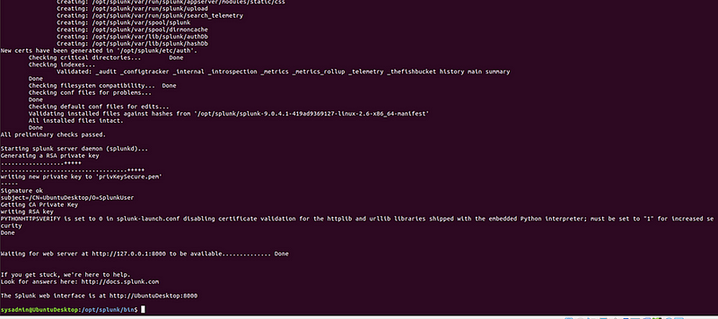
Run the following command to accept the license, and then follow the prompts to enter your username and password
sudo ./splunk start — accept-license
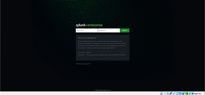
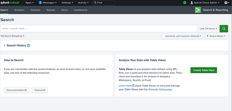
- Access Splunk:
- Open your browser and navigate to http://localhost:8000.](http://localhost:8000.){.markup–anchor .markup–li-anchor data-href=“http://localhost:8000.” rel=“noopener” target="_blank"}
- Log in using the credentials you created.
Go to the Splunk address in your browser, and enter credentials.
- Log in using the credentials you created.
2. Set Up Syslog Inputs
- Configure pfSense Firewall to Forward Logs:
- Log in to the pfSense web interface.
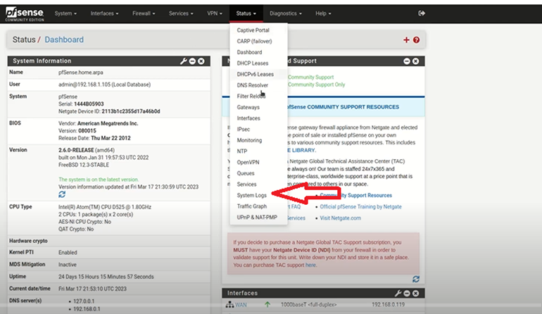
- Navigate to Status > System Logs > Settings.
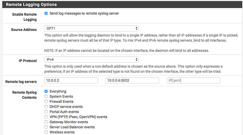
- Enable Remote Logging Options and specify the following:
- Remote log server: IP address of your Splunk server (Kali Linux)
- Port: 514
- Protocol: UDP
- Save changes
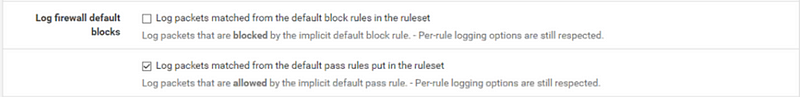
One need to enable ‘Default Allow Logging’.
- To enable logging of allowed packets from the default allow rule, go to to Status > System Logs > Settings tab, then check Log packets allowed by the default rule.
- Click Save to apply the changes.
- Set Up Splunk to Receive Syslog Data:
- In the Splunk web interface, navigate to Settings > Data Inputs.
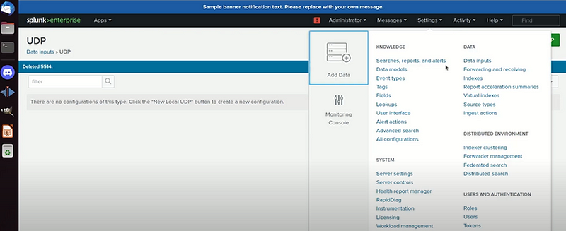
- Under Local Inputs, click Add New for Syslog.
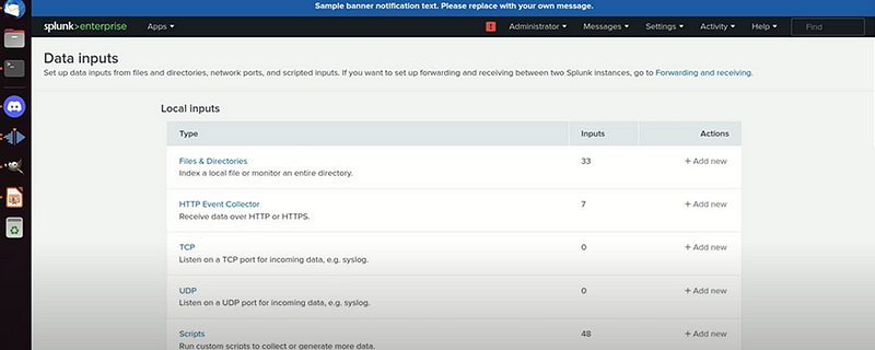
- Configure the following:
- Port: Enter 514 (to match the pfSense configuration).
- Source: Provide a meaningful name, e.g., pfSense_logs.
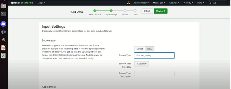
- Host: Choose “Custom” and enter pfSense.
Submit
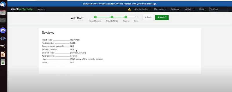
- Save the configuration.
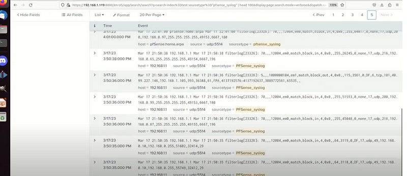
- Verify Syslog Data:
- Use the search bar in Splunk to check for incoming syslog events:
index=_test#
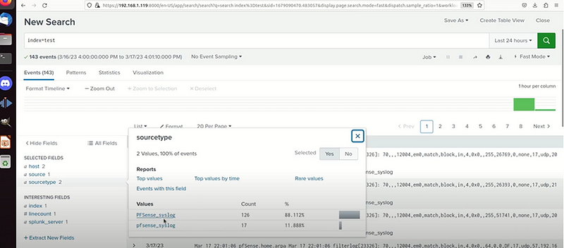
Or index =test sourcetype"pfsense_syslog"#
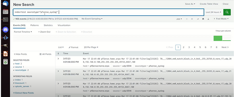
I managed to capture more of syslog pfsense capture
Summary of Implementation:
Network Segmentation with pfSense:
Using pfSense, I created two VLANs: VLAN 10 for general users and VLAN 20 for sensitive systems. Firewall rules were configured to restrict inter-VLAN traffic, ensuring that general users could not access sensitive systems. This segmentation reduces the attack surface and limits lateral movement within the network. Testing confirmed that traffic between the VLANs was effectively blocked, as evidenced by screenshots of the rules and blocked attempts.
Multi-Factor Authentication with google authentocator:
I enabled MFA on a selected application using google authenticator to generate time-based one-time passwords (TOTP). This added an extra layer of authentication beyond just a password. Testing validated that login attempts without the TOTP were rejected, while successful logins required both the password and the Authy-generated code. Screenshots captured the successful MFA setup and usage.
Continuous Monitoring with Splunk:
Splunk was configured to collect syslog data from the pfSense firewall and the MFA-enabled application. A custom Splunk dashboard was created to monitor key metrics, such as user login attempts, blocked access, and network activity between VLANs. Alerts were set up to notify of suspicious activities like repeated failed logins or unauthorized VLAN access attempts. Screenshots illustrated the Splunk configuration and visualized data on the dashboard.
Conclusion:
Implementing these Zero Trust principles — network segmentation, MFA, and continuous monitoring — significantly strengthens CyberTech Solutions’ security by adopting a “never trust, always verify” approach. Network segmentation ensures that sensitive systems are isolated from general users, reducing exposure to potential threats. MFA mitigates risks associated with credential theft, adding a robust second layer of defense. Continuous monitoring enables real-time visibility and rapid response to anomalous or malicious activities. Together, these measures create a cohesive security framework that minimizes vulnerabilities and proactively safeguards the network.
By Kiplagatkelvin{.p-author .h-card} on January 24, 2025.
Canonical link{.p-canonical}
Exported from Medium on February 13, 2025.